Building a Wireless Heart-Rate sensor
I really like using a wired heart rate sensor, but it's a little unwieldy for an installation environment. This post is detailing making a wireless battery-powered transmitter for these modules with the Adafruit Feather NRF.

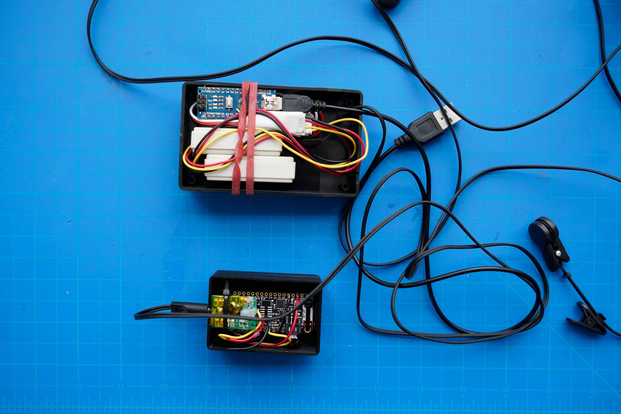
I really enjoy working with SeeedStudio’s wired ear-clip heart rate sensors. However, they are wireless and fairly unwieldy to use for installations because my previous implementation of those sensors required wires to each sensor and a wire back to a host computer or device using USB.
The reason I didn’t just purchase an off-the-shelf Bluetooth heart rate monitor is that I wanted a pretty specific feature: namely, I wanted an ping from the sensor right when the heart rate was detected to allow for experiences that synchronized your heart rate with someone else’s or an sound experience that let you reflect in real time with your detected heart rate. I chose these sensors provided a fairly good pulse signal right when someone’s heart beat.
This project I did over the course of a night and the next morning, most of the time was spent figuring out the enclosure and getting the firmware uploaded to the feather board. Electrically, this was a very simple build.
This describes the process I used to create new bluetooth-based battery-powered sensor modules. I opted to use Adafruit’s bluefruit feather line. Feather boards all include battery-charging and regulation circuitry. The sensor I’m using works with 3.3v so no power boosting is needed for this project. Feathers use a fairly common size and interface as well, simplifying building out enclosures and fit the job well! I used Adafruit’s Feather NRF board (make sure if you’re getting them to get the later model, I already had an earlier model so I used that but the price is the same for the newer model).
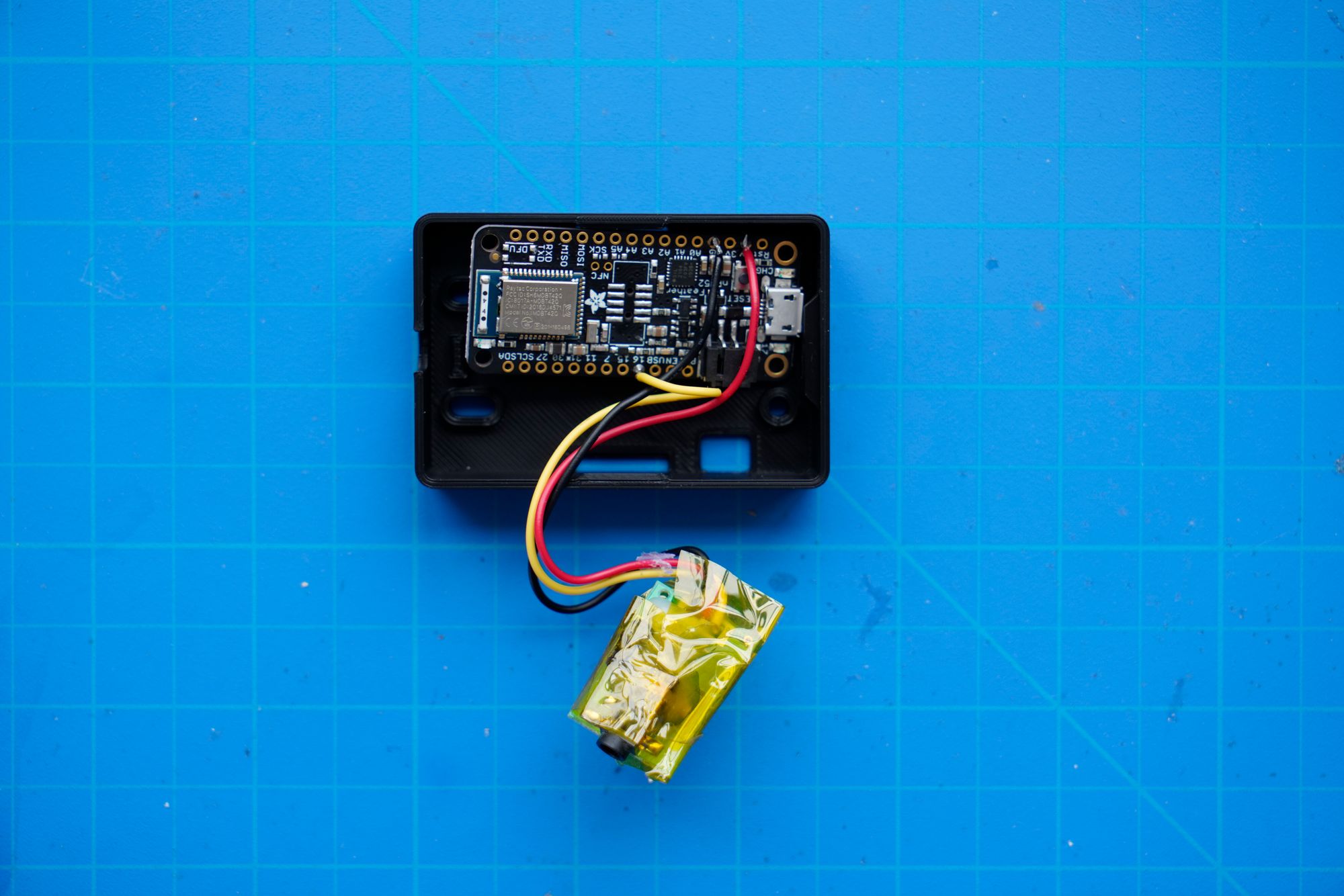
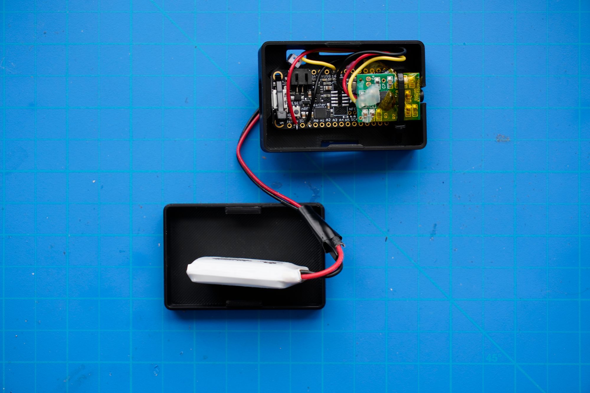
I took apart the plastic case enclosing the receiver module for the heart rate sensor. The module was held in place only by hot glue, easy to remove with a hot air gun set at a low temperature. I then cut the grove connector off of the sensor and directly soldered the pins to the feather. I chose to use GPIO 16, most of the GPIO pins except 13 would be a good choice. GPIO 13 is used for determining the battery level, and we want to use that functionality later.
I then wrapped the sensor module in Kapton tape: it’s used for insulating electronics often and is thin, easy to work with and high-temperature resistant. I used it instead of hot glue to keep a lower profile on the circuit board. The heart rate sensor board has exposed metal and so does the bluetooth module below it, some protection against shorting is needed to keep the enclosure compact.
I then updated some parameters in Adafruit’s official Fusion 360 model for the feather boards, lowering the height and margin sizes to something that more tightly fits this use case. I used a caliper to measure the clearance needed for the battery connectors, boards, and the headphone jack. Since there already was a perfectly-sized cutout on the other side of the board for the headphone jack, only minor sizing adjustments were needed.
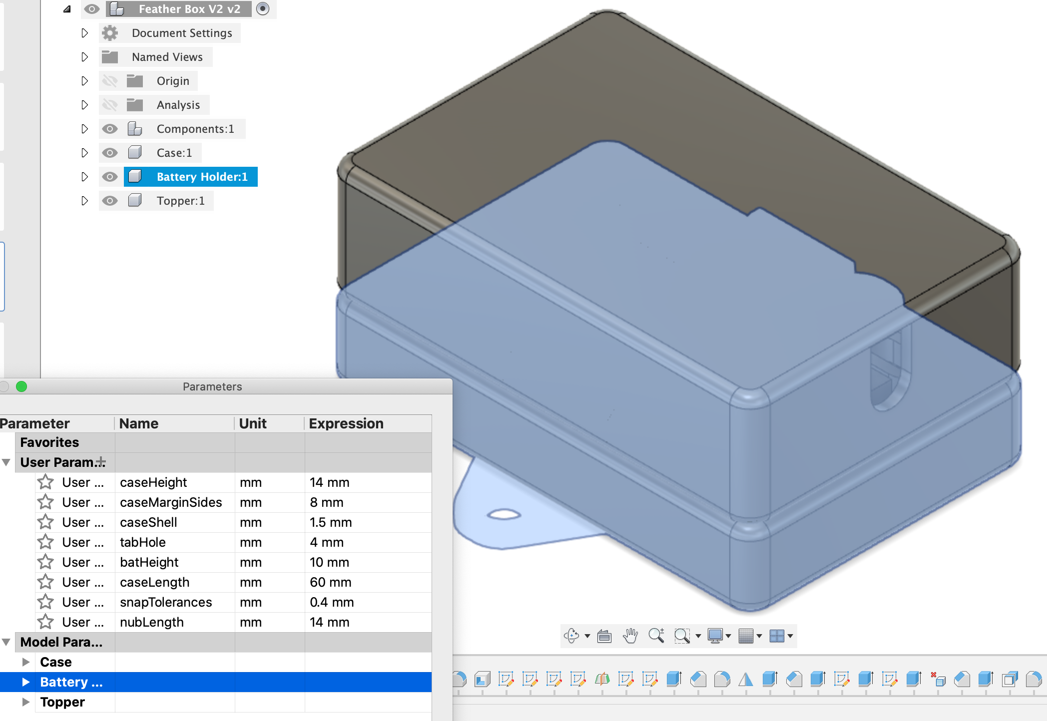
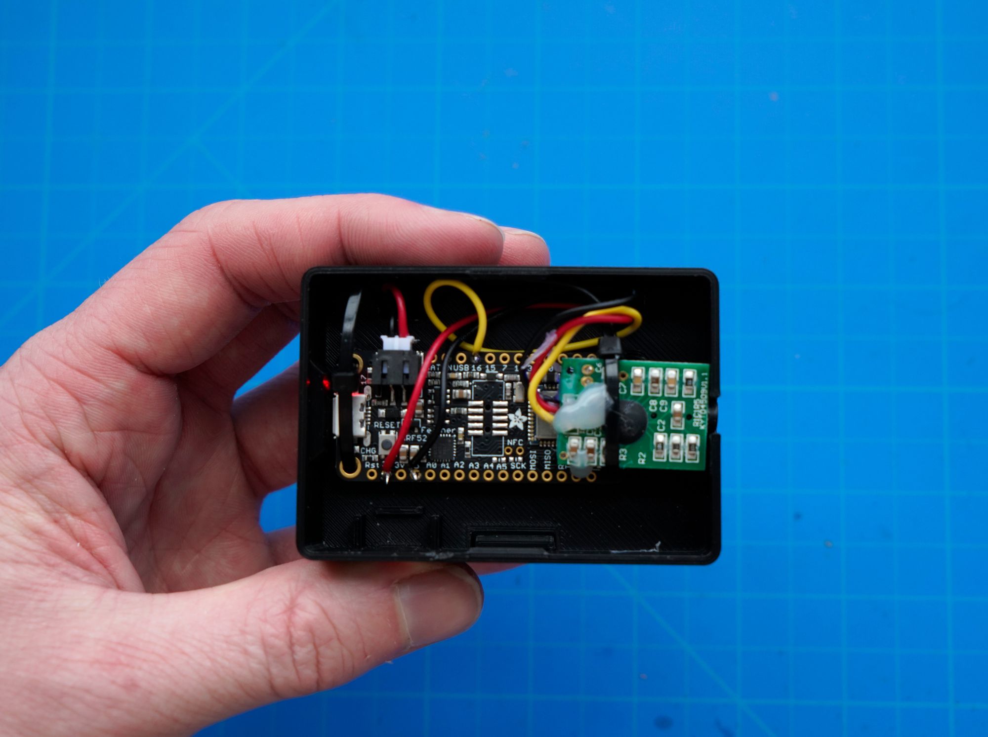
I 3d printed the case with a stock Ender 3 Pro using Cura. I started with the main feather enclosure to ensure the board and wiring fit comfortably before printing the battery section and the top. I left Cura’s settings on a slightly lower quality mode since I didn’t mind small visual defects in the case as long as it worked. A benefit of this mode for me is that the indicator lights showed up a little through the case but dimly, which is good to know it’s working and active but also not distracting as those indicator lights can be very bright.
After 3d printing the case, I realized I didn’t have the proper mounting hardware and just went the easy route: small zip ties! The zip ties fit through all the mounting holes well and did a great job keeping everything together. Since the case was already fairly snug due to the earlier customization, everything fit well even with using zip ties. I also tacked down the heart rate sensor module with a small amount of hot glue to make sure it doesn’t slide around. Changing things tacked down with zip ties and hot glue is quite easy: just either cut the zip ties and put in new ones or slightly heat the hot glue and you can redo your fastening.
The final step here was to setup the battery. The case design had a separate lower snap enclosure for the battery and a hole to run the battery wire from the bottom separation of the case to the top. I used old batteries from drones I had lying around. One thing to be careful about is checking the polarity matches. If the battery has the wrong polarity you can carefully re-solder the wires or connector. Be sure to not plug in any incorrect polarity battery, it’s likely to damage the feather board. Be careful when working with batteries (along with capacitors and solar cells) — they’re usually energized even when sitting around and can catch fire/explode if they become accidentally shorted.
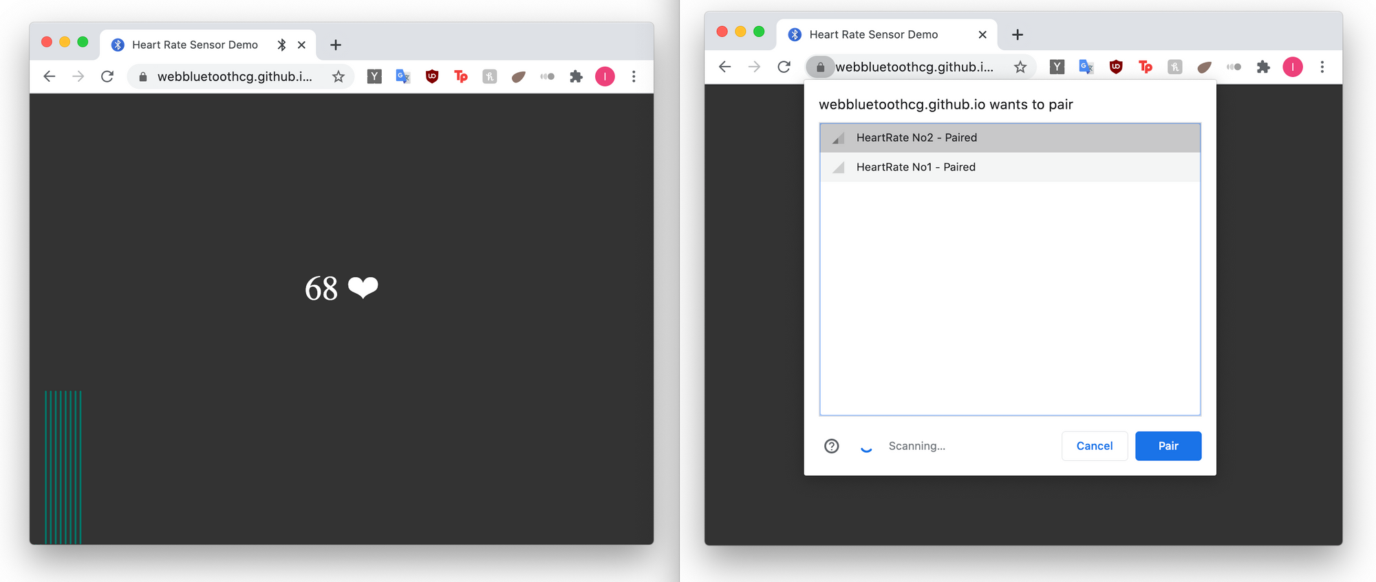
The final step was writing the firmware to send the heart rate over BLE to the client. The architecture is a bit strange: it updates the heart rate on every beat so you can either use the system-aggregated value of heart rate or you can calculate it yourself based off the interval of the messages.
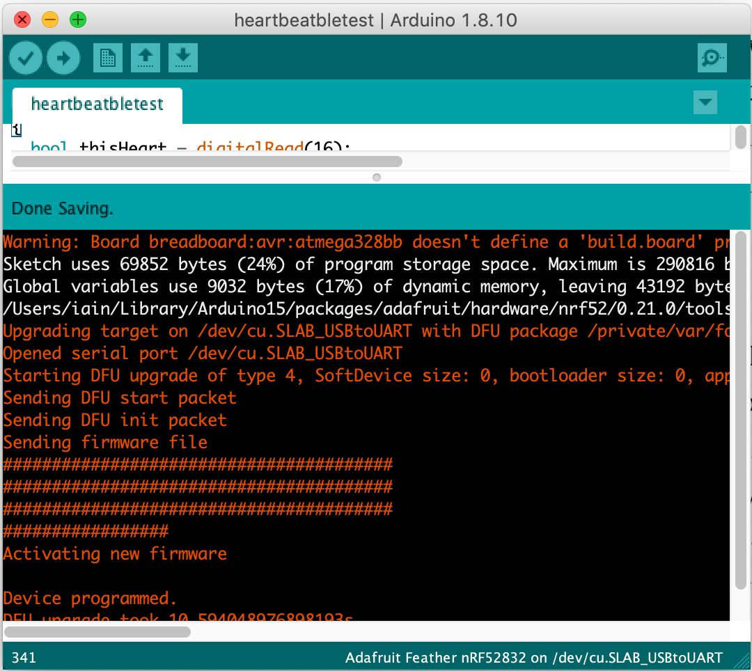
I attempted to use PlatformIo, a general command-line tool and IDE for microcontrollers, but had issues with the uploading DFU (Device Firmware Upgrade) process. After 30 minutes of debugging, I switched over to the Arduino platform with the official Adafruit SDK where I had no issues updating the code on the board. Even though it’s not my favorite UX it’s important to know what is the best supported toolkit for your processors.
Lessons learned:
- Test everything step by step: print the key part first, make everything work outside of the enclosure before mounting or soldering too much
- Think about flexibility for mounting options with prototypes and test if silly ideas work before over-engineering everything
- Be careful when it comes to batteries
- Don’t spend too much time getting platforms to work. I knew that the platform I usually work on isn’t as well supported as another and switching to the Arduino IDE ended up saving me a lot of debugging time for this small project.
All in all, not a bad project in a day.
Some small improvements I’d make moving ahead:
- Give 1–2 mm more clearance at the top of the case for a better fit with flexing the top cover. It works now, but is not that even
- Add a toggle power switch. Right now these modules are on until they die. They don’t use much power and depending on your use case that may be fine. The feather board have a pin that if grounded shuts down the power, which when connected to a toggle switch makes a easy power switch without unplugging or messing with the battery leads.